
- Methodology & deliverables
How We Work — End to End
A good piping stress analysis methodology is not the output of a single software run. It is a documented, repeatable workflow that starts before modelling and continues after the report is issued. Seven steps, ASME-aligned, with a deliverable pack formatted for direct handoff.
A good piping stress analysis methodology is not the output of a single software run. It is a documented, repeatable workflow that starts before modelling and continues after the report is issued. Seven steps, ASME-aligned, with a deliverable pack formatted for direct handoff.
- Methodology
Our Seven-step Methodology
Built on ASME B31.3 and B31.1, using CAESAR II for critical lines. Every decision — from critical-line screening to support selection — is explained in the final report.

Design data validation
We review P&ID, piping isometrics, line list, material specifications, and equipment data sheets for completeness. Any gaps are flagged and closed before any modelling begins. Ninety percent of rework during a piping stress analysis project comes from incomplete or inconsistent input data discovered too late.

Critical versus non-critical screening
Each line is classified as critical (requiring full CAESAR II analysis) or non-critical (suitable for manual cantilever-beam calculation). Screening criteria: pipe size > 2″, design temperature above 150 °C, connection to rotating or sensitive equipment, seismic exposure, or prior incident history.

Model build in CAESAR II
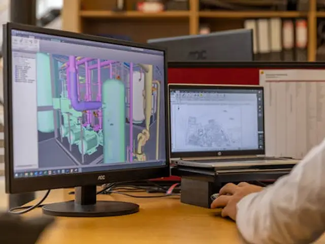
Validated isometrics are rebuilt inside CAESAR II. Supports, restraints, branch connections, expansion joints, and equipment interfaces modelled with the right boundary conditions — not default assumptions. Every model peer-reviewed by a second engineer before load cases are applied.

Load case development & iteration
Sustained, thermal, occasional, and dynamic load cases are built from the operating philosophy, not templates. Iterations continue until every line is within the allowable stress limits of ASME B31.3 or B31.1 and every support sits within its manufacturer’s capacity.

Support & restraint optimization
Supports are selected to manage movement and distribute loads safely. Because Softstra supplies piping hardware through South Moonsgate Sdn Bhd, we know which configurations are actually available and which are specification-only. Spring hanger and expansion joint vendor drawings reviewed before hardware leaves the supplier.

Nozzle & flange verification
Nozzle forces and moments on pumps, compressors, turbines, vessels, and exchangers verified against vendor allowables or the relevant API code (API 610, API 617). Critical flange joints checked for leakage per ASME Section VIII Div 1 Appendix 2 and PCC-1.

Report, isometric markup & handoff
Every engagement concludes with a stress report, support load table, nozzle load summary, marked-up isometric drawings, and an executive summary. Support loads formatted for direct handoff to civil and structural engineers designing the pipe racks.
Inputs We Ask From the Client
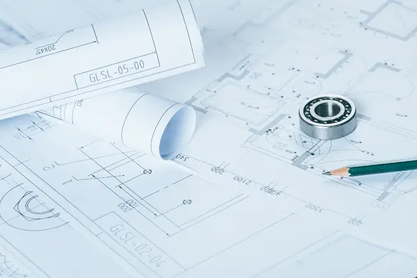
- P&ID drawings (native CAD or clean PDF)
- Piping isometric drawings
- Line list with design / operating pressure, temperature, fluid, material, insulation, corrosion allowance
- Material specification and piping class
- Equipment data sheets with nozzle orientation and allowable loads
- Fired heater tube-sheet and manifold thermal data (if in scope)

- what you receive
Deliverables
Every Softstra piping stress analysis produces the same deliverable structure, scaled to the engagement size. Each stakeholder receives a document they can act on directly.
Core deliverables
- Comprehensive stress report (PDF) with ASME code clause citations
- Equipment nozzle load summary — versus vendor or API allowables
- Flange leakage check summary on critical joints
- Marked-up isometric drawings — support type, location, and load tag numbers
- Executive summary — non-conformances, recommended design changes, residual risks
- CAESAR II model files (native input) — delivered at project close
Optional add-on deliverables
- Spring hanger vendor drawing review — comparison against CAESAR II load and travel envelope
- Expansion joint vendor drawing review — pressure, travel, and spring rate verification
- Piping support fabrication drawings for non-standard supports
- Construction support schedule, indexed to isometric number
- Commissioning stress walk-down checklist
- Post-commissioning stress survey — verification of installed spring hanger travel
Who uses each deliverable
Project engineer / EPC lead
Executive summary and stress report for code compliance sign-off and review meetings.
Civil & structural engineers
Support load table for pipe rack, sleeper, and T-support structural design.
Piping designer / Draughtsman
Marked-up isometrics for support installation detailing and construction package issue.
Equipment engineer / Mechanical lead
Nozzle load summary for verification against purchased equipment vendor data.
Construction / Site team
Marked-up isometrics and support schedule for installation.
Commissioning / Operations
Post-commissioning stress walk-down (optional) and spring hanger travel verification.
Format and Handover Standards
- Reports issued as searchable PDF with bookmarks per line
- Tables exported as editable spreadsheet (XLSX) where required
- Isometric markups returned in client's native CAD format (AutoCAD DWG, PDMS, SP3D)
- CAESAR II native input files included as standard
- Deliverables version-controlled with revision history and change log
- Document numbering aligns with client document control conventions
How We Collaborate
- Kick-off call to align on scope, screening criteria, and document transfer
- Weekly technical call or written update during modelling
- Intermediate review at ~40% completion — model build and load cases reviewed before full iteration
- Final technical review with the client's lead engineer before issuing the report
- Post-issue support for questions, vendor drawing review, and minor revisions
- FAQs
Frequently Asked Questions
We use objective criteria — pipe size greater than two inches, design temperature above 150 °C, connection to rotating or sensitive equipment, seismic exposure, or a history of stress or leakage incidents. Any line meeting one or more criteria is flagged as critical.
Every model is built from validated project isometrics. Material, insulation, and boundary conditions come from project data sheets — never from default libraries.
Every model peer-reviewed by a second engineer before load cases are applied. Final report reviewed with the client's lead engineer before issue.
Yes, as standard. Native CAESAR II input files delivered at project close — enabling future revisions, what-if studies, or operational analyses to start from the verified model.
Yes. Minor revisions (moved support, changed routing) handled within the agreed scope. Significant revisions quoted separately. Deliverable pack versioned with revision history.
- Get in touch
Apply This Methodology to Your Project
Send us a description of the issue, the affected lines, or the project scope.
We come back with a recommended assessment scope and quotation.