
- Service · Cornerstone
CAESAR II piping stress analysis for critical lines.
- Service · Cornerstone
Reliable Piping Systems. Safer Plants. Optimized Designs.
Specialist CAESAR II Piping Stress Analysis for Refineries, Petrochemical Facilities and WHRU Systems.
We provide specialist piping stress analysis services to owner-operators, EPC contractors and engineering consultants, helping them deliver safe, reliable and cost-effective piping systems throughout the project lifecycle.
Our solutions focus on equipment protection, code compliance, thermal flexibility and long-term plant reliability.
Why Piping Stress Analysis Is Essential
Industrial piping systems are continuously subjected to various loading conditions during operation, start-up, shutdown and upset scenarios.
Loads include:
- Internal pressure
- Pipe, fluid and insulation weight
- Thermal expansion and contraction
- Wind and seismic loading
- Equipment nozzle movements
Without proper stress evaluation, piping systems may experience:
- Excessive nozzle loads
- Pipe overstress
- Weld cracking
- Flange leakage
- Pipe support failures
- Thermal expansion clashes
- Excessive displacement
- Equipment damage
- Unplanned shutdowns
Piping stress analysis ensures adequate flexibility and structural integrity.

Why Invest In Piping Stress Analysis
Improve Plant Safety
Reduce risk of failures and leaks.
Protect Critical Equipment
Pumps, vessels, exchangers, WHRU coils.
Reduce CAPEX
Optimized supports and reduced steel.
Reduce OPEX
Less rework and downtime.
Increase Plant Availability
Improved reliability.
Ensure Code Compliance
ASME B31.3, B31.1, ASME VIII, EN 13480.
Caesar II Analysis Capabilities
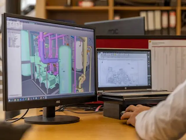
Every critical line is rebuilt inside CAESAR II from validated isometric drawings. The model includes pipe routing, wall thickness, fluid and insulation weight, supports, restraints, branch connections, expansion joints, and the boundary conditions at equipment interfaces.
Static Stress Analysis
- Sustained load: Assesses weight, pressure and constant forces to prevent structural sagging and buckling
- Expansion load: Analyzes displacement strains from thermal growth to prevent thermal fatigue.
- Occasional load: Evaluates unpredictable wind, seismic and relief valve forces.
Thermal Expansion Analysis
- Flexibility checks
- Thermal movement
Nozzle Load Assessment
- Equipment protection
- Vendor limit compliance
Pipe Support Optimization
- Guides, stops, springs
- Structural interface
Brownfield Assessment
- Modifications and tie-ins
Failure & Integrity Assessment
- Flange leakage assessment
- Assessment of code overstress conditions
- Pipe support integrity
- Engineering recommendations
Industries
Refineries
Petrochemical Plants
LNG Facilities
Gas Processing Plants
Fertilizer Plants
WHRU Units
Offshore Facilities
Power Plants
Brownfield Projects
Deliverables
In the stress report, we shall report
- Code compliance summary
- Displacement report
- Restraint summary (extended)
- Nozzle load report (where applicable)
- Flange leakage report
- Stress isometric markups
- Fully compiled calculation results attached as Appendices
- FAQs
Frequently Asked Questions
A single critical line typically takes 2–5 working days once inputs are validated. A package of 20–30 critical lines is normally completed in 4–6 weeks.
Both. B31.3 applies to process piping (refineries, petrochemical, chemical). B31.1 applies to power piping (steam, HRSG, WHRU). We confirm the governing code during scope-setting.
Yes. Manual calculation on manifold-tubesheet expansion and nozzle movement is a Softstra specialty. The manual result is integrated into the CAESAR II model of the connected piping as displacement load cases.
Yes. Softstra supplies engineered pipe supports, spring hangers, expansion joints, flanges, and gaskets to the specifications produced in our analysis. Optional — clients may also take the spec to their preferred vendor.
Yes. Reviewing vendor submittals is part of our standard scope and can be included or quoted separately.
Yes. The support load table is formatted for direct handoff to civil and structural teams designing pipe racks, T-supports, and sleepers. No translation step required.
- Get in touch
Start Your CAESAR II Piping Stress Analysis
Send us your line list, P&IDs, or a short description of the scope.